Lunar Energy: LED interaction engineering
A design engineering case study - helping designers design and prototype physical interactions for real-world deployment
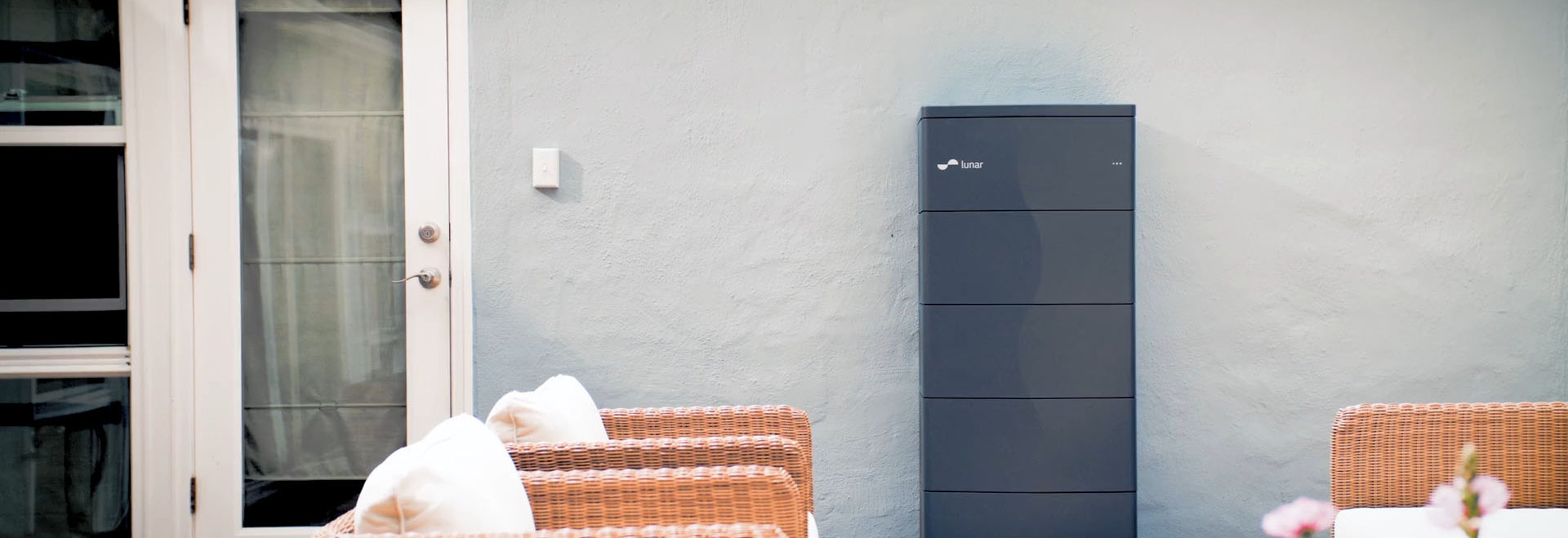
The Lunar Inverter and Battery in situ
Lunar Energy make the Lunar System, a domestic battery system for solar panels. The primary interaction platform for this is a mobile app that customers will use to monitor and control their battery setup. The battery exterior is stylishly minimal, bare except for a logo, and, at the top right, three coloured lights.
These lights - RGB LEDs - also communicate the state of the device. They’re particularly important when the app might not be usable or connected to the device - during commissioning, initial setup, or when there’s a problem with the system.
The design team at Lunar reached out to me to help them build a tool to help them design, test, and validate display patterns on the real hardware.
What follows is a great case study of a “design engineering” problem: the work is engineering, in the service of design. Delivering on this brief required juggling design and engineering roles to consider not only what to build, but how to share it with an audience of designers, and how to give them the controls they might need, without complex technical overhead.
The Brief
Lunar already had initial designs for the LED displays made in graphics tools, and had conducted research with installers and engineers. But they now wanted to validate their designs in reality, on the real LEDs, in real fascias, behind real lightpipes in outdoor lighting conditions - all variables that might affect their design choices. And they needed to able to rapidly iterate and adjust these designs. What would assist would be an easy-to-use tool that would let designers configure these patterns, and then provide a precise spec for them to the engineering team.
The Approach
At the project kick-off, I shared my understanding of the brief with the client, showing an approach building the two components of the tool:
- a test harness that would connect to the real LED board that Lunar had supplied, and display the patterns. This needed to be cheap and robust, and it should be possible to make multiples with little extra effort - so that there were spares, and so that harnesses could easily be shared with colleagues. This test harness needed to be able to run the scenes without being connected to a computer. This would allow the device to be programmed over a cable, and then the computer disconnected whilst a designer walks to the other end of a yard or garden to observe the results in a realistic outdoor setting.
- an editor to design the patterns. This needed to work with as little friction as possible (ie: no installing of drivers, no command-lines, no compilers). It should also be easy to duplicate ideas to create variants, and to share data with other team members.
I also emphasised what I felt was a critical aspect of the tool: it had to be completely usable without me. I was going to deliver the tool long before the design work was finished; as such, any hardware should be easily replicable, and any software usable without further modification.
The Test Harness
The initial test harness
I started with the test harness. The very first task to confirm I could communicate with the LED daughterboard I’d been supplied with.
I used the Raspberry Pi Pico as my microcontroller development platform. I love using the Pico: it’s cheap, reasonably powerful, and has many flexible peripherals. I develop for it in the Pico C++ SDK, which is quick to work with and has excellent documentation.
The daughterboard had just three pins: power, data, and ground, and the data pin took the data that is typical of addressable RGB LEDs such as the WS2812. There is a great deal of sample code available for these, and the Pico’s PIO pins are particularly suited to driving them. This made it quick to get a quick ‘proof of life’ demo of some animations running.
The Editor
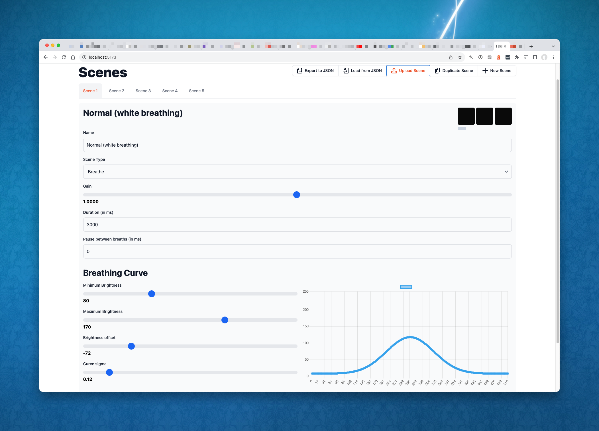
The editor, showing a 'breathing' scene
Before I could design the editor, I had to design an abstraction for the patterns - something that could represent all possible patterns as data. This abstraction would then be represented in two data formats: one for the editor, based on JSON, and a list of bytes, to be used by the hardware.
I named this abstraction a Scene.
Lunar’s initial scene designs all fell into one of two categories:
- breathing scenes, similar to the classic Macbook charging light: a gentle pulse, whether that was from “off to a colour” or “light to dark shades of a single colour”. The speed of the breath and which LEDs were engaged would need to be changeable, as well as the colour, and the brightest/darkest levels.
- frame animation scenes, where the pattern could be described as a series of individual frames - think of a ‘scrolling’ light, appearing to move across the display. Each frame would describe which LEDs were on, what colour they were, and how long they were on for.
I shared this abstraction with the team, and they confirmed it would meet their needs. I could now build the editor in confidence.
Once, the editor might have been a desktop app, or a Processing sketch, that would then communicate with the hardware over a serial port. In 2023, we have a slightly easier approach: the web browser.
The WebSerial spec provides a specification for talking to a USB serial port from within a web browser. Chrome is the primary browser that supports this; whilst it may not be particularly ‘web-like’, it’s brilliant for building these small tools to talk to local hardware.
I’d build a front-end only UI in SvelteKit (see my write-up of a year working with SvelteKit). This would store data in the browser’s localStorage, allow users to save and load scenes to JSON files, and transmit scene data over serial to the hardware. I kept the UI as simple as necessary, building a ‘working wireframe’ style UI with off-the-shelf libraries like Flowbite and ChartJS.
The editor previewing a 'frame animation' scene
At one point I spent some time building a little ‘realtime preview’ in the browser, to visualise patterns without even needing a device. As I was writing this feature, I wondered if it was unnecessary polish.
It turned out to be a hugely useful piece of work. It let me prototype the math for the breathing algorithm (a kind of normal distribution, with a number of controls), and let me work out how to code the display of frame animation in an environment well suited to prototyping. I worked out all the logic in Typescript, the browser hot-reloading as I went. When I later came to implement the scene animation logic in C++ on the Pico, the work was to port the existing code to C++, rather than having to do invention work in the more complex (and less dynamic) language. The work on the preview tool ended up saving me a good deal of time on the firmware.
Bridging hardware and software
With the editor tool in a good place, I returned to the firmware. I added code to receive editor data over serial, storing the new ‘scene’ in built-in flash memory (with simple wear-levelling). I spent ran into some tricky bugs with my code for receiving longer, multi-part serial messages; these were eventually solved with the aid of a debugger and the Pico Debug Probe.
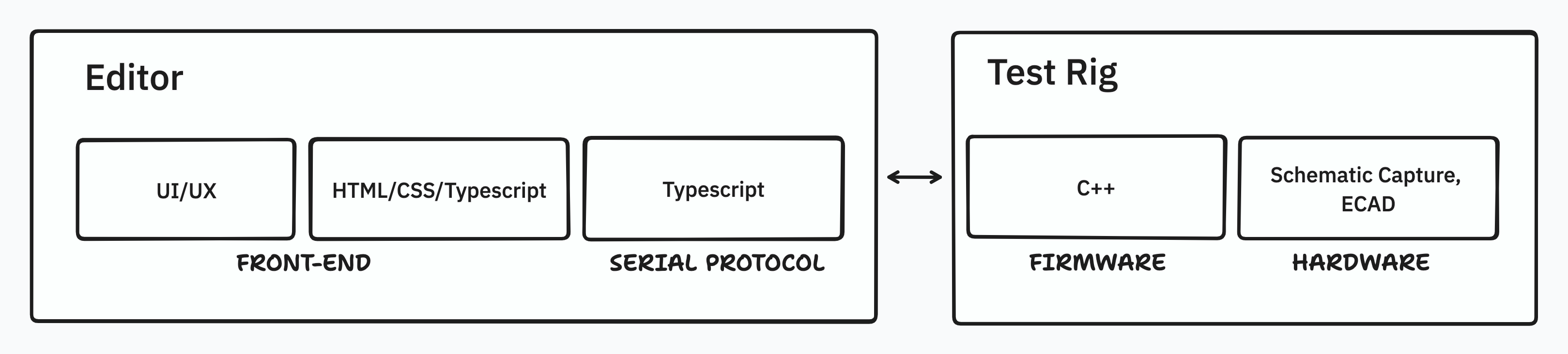
The project stack
There is always a kind of whiplash as you move between tools, languages, and abstractions in a project like this. New editor functionality written in HTML, CSS, and Typescript would require changes to the C++ firmware - perhaps even changes to the CAD of the final board; evaluating the results might lead me to have to update the editor, changing the data to be sent, or even revising the UX of the editor itself.
This is not a problem; it’s a necessity for this kind of work. But it means holding a lot in one’s head simultaneously, and creating an environment where it’s easy to mode-switch like this. For me, that means keeping detailed documentation, so I can remember as little as possible, and instead just look things up.
A Final Board
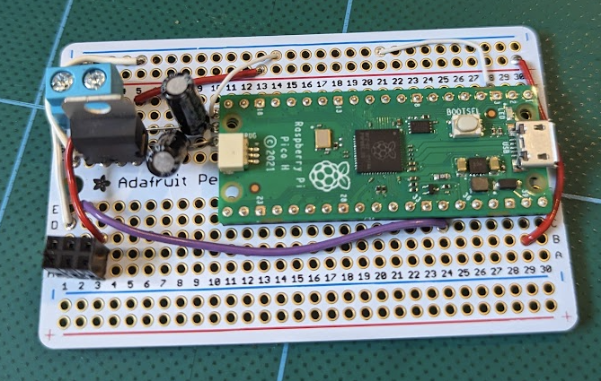
The "perma-proto" test harness
At this point, the development board existed as a Pico soldered to a “Perma-Proto“ board - a printed circuit-board laid out like a little breadboard. As well as the Pico, there was a small voltage regulation circuit. The daughterboard ideally takes 13V as its power supply, which it steps down to +5V. My board would take 13V in, sending it out to the LED board, and stepping it down to 5V to power the Pico’s VSYS input. I also hadded a little protection to ensure that when connected over USB, the Pico’s little regulator wouldn’t try to back-power anything.
Rather than making any more of these, I suggested that we build up real printed circuit boards for the test rig. This would make it far easier to share with other designers, and more robust.
I’d been keeping track of the test-rig circuit schematic in KiCad; after all, the easiest way to draw a schematic is in a schematic-capture tool. With the schematic already up-to-date, I had everything I need to make a board layout. To make the boards robust, I put power connectors on both screw-terminals and large pads suitable for crocodile clips, and a simple header connector for the LEDs. On the rear of the board, I added useful tips on correct usage of the board to the silkscreen.
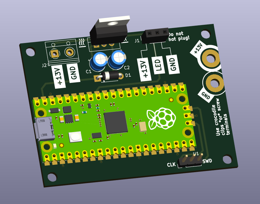
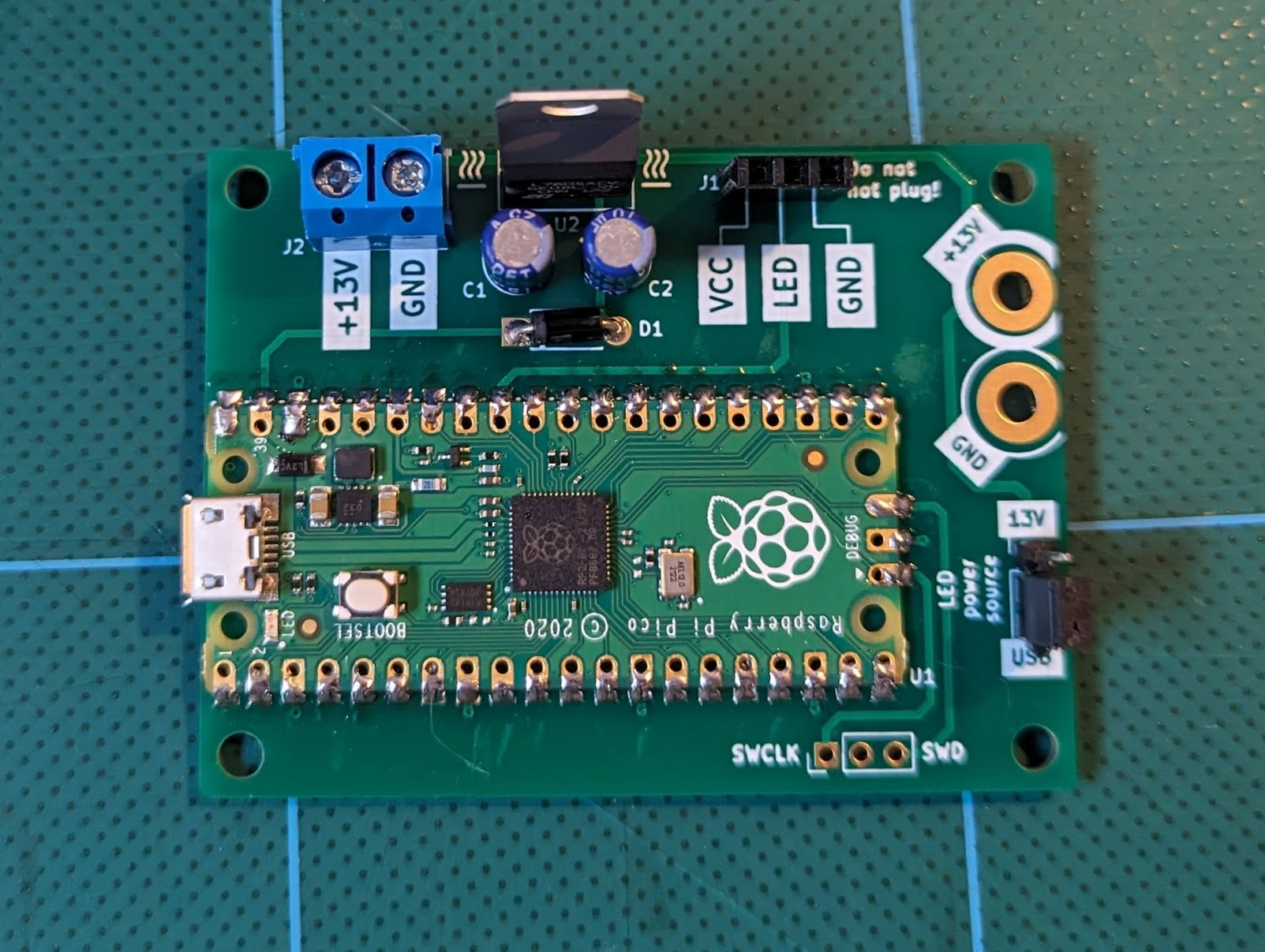
KiCAD render, and final board - note the added 13V/USB jumper
I always tend to sleep on a board design before sending it to fabrication. This is usually because I catch any mistakes much more easily after some time away from it. But in this case it led to one extra feature: a jumper to toggle the LED power supply between the external 13V source and the USB 5V source. This jumper would let designers use the test rig without requiring a bench power supply to do so. (They could still swap over to 13V power for final testing).
This also had the neat side effect of allowing the test-rig to be powered from a USB battery pack - which turned the whole thing into a neat prop/demonstrator, ideal for using on photo or film shoots, or at trade events.
Outcomes
I like to organise demos early, as soon as I have something end-to-end, so we can gather feedback and make appropriate course corrections. We reached that initial demo of a simple test rig and editor after a few days of work. It confirmed that we were heading in the right direction, and the feedback led to new functionality - adding the possibility of different breathing curves for each scene, as well as quality-of-life features within the editor.
As the work came to the end, I shared the possibility of fabricating multiple boards for the design team, and Lunar commissioned a little extra work to get the final boards produced.
Matt, head of design at Lunar, introduced me to his colleagues by saying
“Tom has a whole little design studio in his head, all talking to one another”
which is very flattering, but also describes exactly what this shape of work requires: holding design, software, and hardware engineering in mind simultaneously, leaping between the roles as needed, and throughout the process, collaborating and sharing with a client openly.
Lunar were great to work with throughout, and they picked up the tool and put it to use immediately. The project is a great case study of tightly coupled design and engineering informing one another.